555 Timer Inverter Circuit Diagram
Inverter 100w Circuit astable timer transformer Inverter 555 ic circuit circuits diagram homemade its explored astable implementing oscillator wherein function mode standard source used
555 Timer Schematic Diagram - Astable Multivibrator Using 555 Timer
Multisim timer 555 astable circuit diagram timer multivibrator circuits calculator using electronic led mode off formulas time 555 timer astable multivibrator circuit diagram
Inverter ic 555 timer cfl 230v ne555
Inverter 555 timer circuitsInverter circuit voltage schematic diagram using circuits ne555 generator ups power ic 6 best ic 555 inverter circuits exploredMake simple 555 inverter circuit using mosfet.
Inverter 555 schematic timer circuit mosfet output signal homemade electronoobs circuitos12v to 230v inverter circuit diagram using 555 timer ic » inverters 12v power inverter using 555 timer555 timer internal circuitbasics astable multivibrator.

555 timer inverter circuit
Timer schematic circuitspedia bistable astable monostable circuit555 timer schematic diagram Circuit ic inverter pwm processor circuits simple generator adjustable bridge homemade driver sine pure waveTimer 555 circuit schematic electronic circuits control ic relay using simple charger next board battery timing basic driver schematics.
555 inverter timer diy wave circuit schematic square potentiometer output adjust electronoobs circuitos555 timer ic inverter 12v to 220v ~ electronics lab Inverter 555 circuit timer 220vac 12vdcUsing 555 timer ic as pwm generator.

Simplest power inverter circuit using a single 555 ic
555 timer ic ne555 block monostable circuits multivibrator ws tutorials waveforms resistance dividers tester ics mv happens working bistable timmer555 timer ic electronic circuit astable multivibrator integrated 555 timer inverter circuit555 timer ic pin diagram features and applications.
Inverter schematic diy circuit timer final square circuitos electronoobsInverter arduino Schematic lab engineering pwm timer diagramVoltage inverter using a 555 schematic circuit diagram.

How to make 100w inverter using 555 timer ic
Inverter mosfet ne555 power using circuit 220 volts 555 diagram ic simple make timer 50hz wave output frequency use generatorResistance and voltage dividers « the blog at the bottom of the sea Inverter timer circuit power 600w diagram explanation555 inverter timer circuit 12v ic schematic 220v diagram.
555 timer ic astable multivibrator circuit circuits integrated datasheet chips electronic diagram save6 best ic 555 inverter circuits explored Diy 555 inverter timer circuitPower inverter with 555 timer.

Homemade inverter diy arduino 555 timer circuit
230v simple inverter circuit using 555 timerDiy 555 inverter timer circuit Inverter 555 ic timer 230v 240vFree circuit diagrams: timer 555 schematic.
Inverter circuit ic timer electronics lab diagram 12v 220vDiy 555 inverter timer circuit Inverter circuit diagram using 555 timer555 timer ic inverter circuit schematic 12v to 220v ~ electronics lab.

My first (working) 555 transformer driver circuit
Inverter circuit 555 ne555 ic using power circuits single simplest wave diagram output bridge square type will homemade explored projects .
.


555 Timer Astable Multivibrator Circuit Diagram

Inverter Circuit Diagram Using 555 Timer - Home Wiring Diagram

DIY 555 inverter timer circuit

555 timer IC Inverter circuit schematic 12V to 220V ~ ELECTRONICS LAB

Using 555 Timer IC As PWM Generator - Engineering LAB
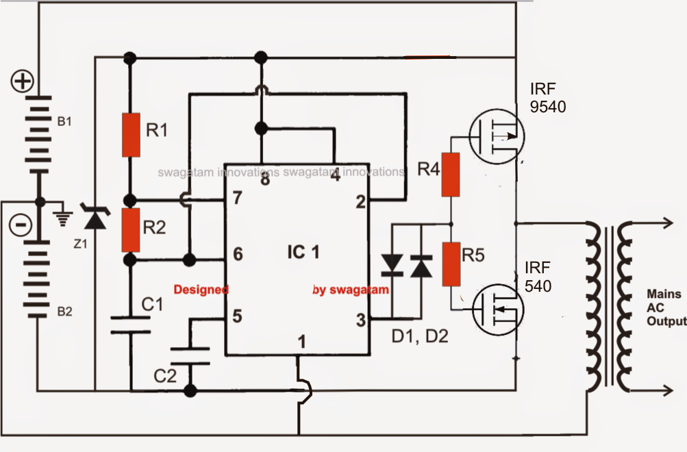
Simplest Power Inverter Circuit Using a Single 555 IC | Circuit Diagram