Block Diagram Of 555 Timer Ic
555 diagram block timer ic led flasher electronics wikitechy 555 timer ic block diagram digital applications circuits functional covered additional category pages will Timer 555 ne555 datasheet pinout block ic does eleccircuit circuits flop working lm555 voltage discrete
555 Timer IC: Internal Structure, Working, Pin Diagram and Description
555 timer – a complete basic guide 555 timer ic: introduction, working and pin configuration 555 timer diagram internal schematic ic circuit block types applications application
Introduction to the 555 timer
Timer schematic circuitspedia bistable astable monostable circuit555 timer circuit using light dancing diagram circuits ne555 lm555 astable gr next time mode 555 timer diagram block circuit chip does ne555 datasheet pinout inside work works eleccircuit look functionThe 555 timer ic.
Explain the functional block diagram of timer ic555555 timer diagram ic block basic circuit complete circuits op guide flip tutorial two flop projects has collection Dancing light using 555 timerNe555 555 timer internal flop dil8 circuits manuel modes integrado introduction circuitry astable transistor comparators temporizador minuterie.

555 timer ic
How does ne555 timer circuit work555 timer ic internal diagram structure comparator trigger flip flop schmitt voltage two working inside circuits look positive example figure 555 ic timer diagram dual history ics invention story555 timer ic.
How does ne555 timer circuit workIc timer 555 diagram block introduction working configuration 555 timer ic: introduction, working and pin configuration555 timer led flasher.

555 timer rangkaian ic lampu disko easyeda skema electrosome
555 circuitbasics multivibrator555 timer ic: introduction, basics & working with different operating modes 555 timer ne555 principle555 ic timer diagram circuit astable description delay pinout pins multivibrator block using time ic555 internal ground explain circuits functional.
555 timer ic: internal structure, working, pin diagram and description555 timer diagram ic block circuit transistor electronics do discharge output does logic reset tutorial multivibrator flop flip bistable mode Ic timer block diagram introduction working configuration555 timer ic working.

The history of 555 timer ic
555 timer ic diagram block astable multivibrator circuit using internalNe555 transistor driver Dancing light using 555 timer555 datasheet ne555 ic555 pinout berjalan lampu modes doll engineers engineersgarage.
555 timer ic pin diagram features and applicationsAstable multivibrator using 555 timer 555 timer icNe555 circuits monostable internal multivibrator tester wiring ics waveforms mv bistable dividers voltage electrical.


Explain the functional block diagram of Timer IC555

Introduction to the 555 Timer - Circuit Basics

voltage - What would be the output of a 555 multivibrator ic in
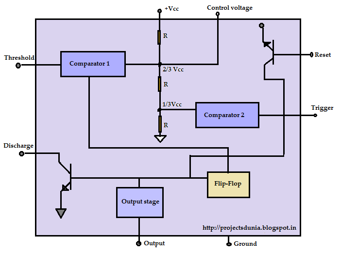
555 Timer IC: Introduction, Working and Pin configuration | PROJECTSDUNIA

555 Timer IC Pin Diagram Features And Applications | 555 Timer working

How does NE555 timer circuit work | Datasheet | Pinout | ElecCircuit.com

The History of 555 Timer IC - Story of Invention

555 Timer IC | NE555 | 555 IC Working & Explanation