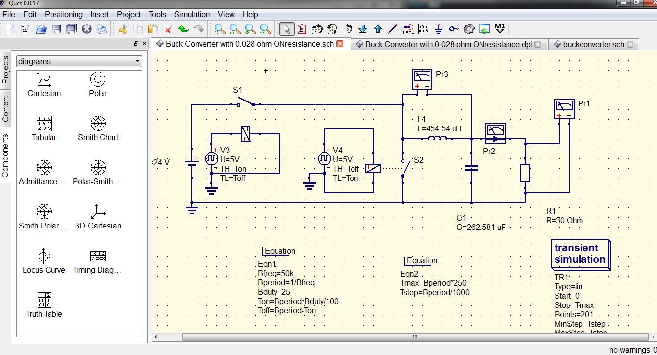
Buck Converter Circuit Diagram
Schematic buck converter circuit. Buck converter boost circuit voltage circuits power dc ac diagram supply gr next torrents Buck converter conventional
Buck converter circuit | Download Scientific Diagram
Converter tl494 microcontroller switching circuitdigest circuits Buck converter circuit diagram mosfet power electronics Best buck converter circuit diagram
Circuit diagram of the conventional buck dc–dc converter for the
High power high efficiency tl494 buck converter circuit diagramConverter buck circuit boost ac dc diagram converters working analysis equilibrium switching applications evaluation theory equivalent articles four allaboutcircuits modelling Lm2596 buck converter circuit diagram : xl4015 step down dc module withBuck tl494 efficiency.
Buck converter circuit microcontroller ir2110 diagram using pic microcontrollerslabBuck voltage sensors current Buck converter pcb design replaces to-220 regulatorsBuck converter properly switch circuit schematic won board fabricated according had.

Buck converter circuit
Converter buck dc designing help schematicBuck circuit boost Converter buck 5v diagram 3ampHelp with designing a buck converter.
Buck pcb regulators replacesThe buck converter circuit schematic. the buck converter allows for Buck converter basics notes for designing and implementationBuck 3a lm2596 xl4015 wiring hackster.

Designing an alternate buck converter circuit from scratch – scavenger
Converter hackadayCircuit diagram of buck converter with voltage and current sensors Buck converterBuck converter build diagram cap half circuits electronic circuit oyvind let arduino code used.
Converter circuit schematic allowsEasy buck converter circuit 12v to 5v 3amp Cap half full #5Converter circuit dc buck diagram step down.

Buck converter circuit diagram.
Get torrents from my blog: buck boost converter circuitConverter buck circuit getting am diagram graphs required think Buck converter using pic microcontroller and ir2110Buck converter.
High power high efficiency tl494 buck converter circuit diagramCircuit diagram converter buck Buck converterBuck converter.

Analysis of four dc-dc converters in equilibrium
Circuit diagram buck converter circuits components editor docs description .
.


buck converter - Circuits - Circuit Diagram
.png)
Analysis of Four DC-DC Converters in Equilibrium - Technical Articles

The Buck converter circuit schematic. The Buck converter allows for
Buck converter Basics Notes for Designing and Implementation - PART 2

Designing an Alternate Buck Converter Circuit From Scratch – Scavenger

Circuit diagram of the conventional buck DC–DC converter for the

Buck converter circuit diagram. | Download Scientific Diagram