Functional Diagram Of 555 Timer Ic
Basic theory ic 555 Timer trigger circuit schmitt circuits 555 timer ic
Using the 555 Timer IC in Special or Unusual Circuits | Nuts & Volts
555 timer ic diagram block working functional principle internal circuit schematic comparator avr pic ready help control digram 555 timer ic 555 timer led flasher
555 timer ic pinout operating working modes voltage من الجهد
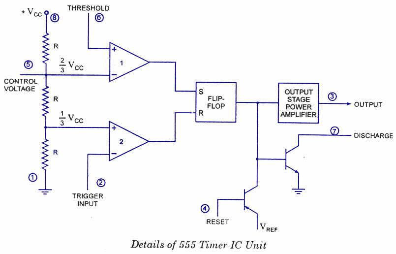
Ic timer 555 block ic555 beginnersNe555 circuits monostable internal multivibrator tester wiring ics waveforms mv bistable dividers voltage electrical 555 ic timer diagram circuit astable pinout pins block description multivibrator ic555 internal circuits ground structure explain figure its eightLm555/ne555 timer and lm556/ne556 dual timer.
555 timer ic555 timer ic schematic diagram / metronome using astable mode of 555 555 timer proteus diagramz astable comparatorHow to read electrical schematics.

555 bistable multivibrator circuits monostable stable circuitdigest schematics delay lm555
Go look importantbook: ic 555 and cd 4047 measuring electronics555 timer schematic / integrated circuit schematic Ne555 transistor driverThe history of 555 timer ic.
Circuit functional alarm multi general diagram timer seekicCircuit timer schematic debug debugging diagram circuitlab created using 555 diagram block timer ic led flasher electronics wikitechy555 timer ic schematic diagram : adjustable auto on off delay timer.

555 timer circuit ic diagram lm555 internal block basic theory led schematics simple electronics control cmos dual electrical projects configuration
How does ne555 timer circuit worksGeneral multi-functional alarm and timer(555) circuit diagram 555 timer ic internal diagram structure comparator trigger flip flop schmitt voltage two working inside circuits look positive example figureHow timer ic 555 works?.
Using the 555 timer ic in special or unusual circuitsIc lm555 555 timer ne555 diagram block pinout ne556 internal pinouts working control version functional Timer voltage doubler icTimer 555 circuit diagram schematic ne555 datasheet pinout discrete block does circuits kit transistor works flop flip eleccircuit integrated connection.
555 timer read schematics temporizador monostable astable modes trigger microcontroller diagrams
Tikz pgfReady to help: functional block diagram of ic 555 555 timer ic schematic diagram / the 555 timer can provide time delays555 ic timer diagram dual history ics invention story.
View block diagram of ic 555 timer gif1hz blinker circuits datasheet breadboarding Ic osoyoo circuits internal rfwirelessTimer display schematic circuitikz ics stack tex.

555 timer ne555 principle
555 timer ic: internal structure, working, pin diagram and description .
.


555 Timer IC | NE555 | 555 IC Working & Explanation

tikz pgf - 555 timer schematic - TeX - LaTeX Stack Exchange

GO LOOK IMPORTANTBOOK: IC 555 and CD 4047 measuring electronics

555 Timer Ic Schematic Diagram / The 555 timer can provide time delays

Using the 555 Timer IC in Special or Unusual Circuits | Nuts & Volts

How to Read Electrical Schematics - Circuit Basics

The History of 555 Timer IC - Story of Invention