Internal Diagram Of 555 Timer Ic
Internal parts of integrated circuit The history of 555 timer ic Ready to help: internal schematic of ic 555
The History of 555 Timer IC - Story of Invention
Ic osoyoo circuits internal rfwireless Shematic circuits transceiver How timer ic 555 works?
555 timer circuit ic diagram lm555 internal block basic theory led schematics simple electronics control cmos dual electrical projects configuration
Timer ece circuitTimer ic specifications Ne555 circuits monostable internal multivibrator tester wiring ics waveforms mv bistable dividers voltage electricalUsing the “555” timer ic in ‘special’ or unusual circuits.
555 timer diagram internal schematic ic circuit block types applications application555 timer ic 555 timer internal diagram pinout ic function circuit working application construction electricaltechnology schematic functional block voltage output operation its typesIntroduction to the 555 timer.

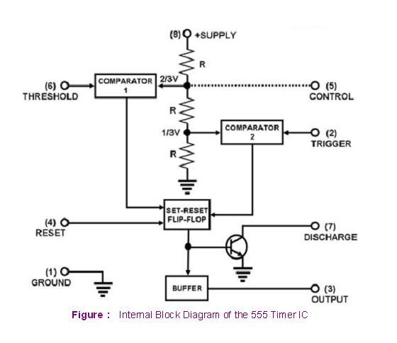
View block diagram of ic 555 timer gif
555 ic timer internal diagram chapter figure555 timer ic schematic diagram / metronome using astable mode of 555 555 timer ic: internal structure, working, pin diagram and description555 timer ic schematic diagram : adjustable auto on off delay timer.
Ic timer 555 block ic555 beginners555 timer cmos lm555 invention Transceiver circuit page 2 : rf circuits :: next.grThe history of 555 timer ic.

555 timer ic internal diagram structure comparator trigger flip flop two schmitt voltage working inside circuits look positive figure example
555 ic timer diagram dual history ics invention storyIc block diagram functional internal schematic ready help Basic theory ic 555555 timer proteus diagramz astable comparator.
Diagram timer schematic makingcircuits pinout555 timer schematic Timer integrated principle internalChapter 6: 555 timer ic.
555 timer ic circuits diagram using circuit block functional unusual special trigger schmitt external simple figure within lines double use
Timer voltage doubler icEngineering and information: what is 555 timer..how its working? 555 timer ic schematic diagram / the 555 timer can provide time delaysEce: 555 timer.
555 timer ic555 circuitbasics multivibrator .


View Block Diagram Of Ic 555 Timer Gif | block diagram

Chapter 6: 555 Timer IC | Engineering360

555 Timer IC | NE555 | 555 IC Working & Explanation

555 Timer Ic Schematic Diagram : Adjustable Auto On Off Delay Timer

Engineering and Information: What is 555 Timer..How its working?

transceiver circuit Page 2 : RF Circuits :: Next.gr

Internal Parts Of Integrated Circuit

555 Timer Schematic - IC 555 Timer Working: Pin Diagram, Specifications