Pin Configuration Of 555 Timer
Ic configuration timer avr pic microcontroller projects 555 timer configuration ic diagram specifications dip ne555 pinout chip working electronicsforu The history of 555 timer ic
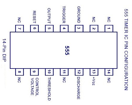
8051- AVR - PIC MICROCONTROLLER PROJECTS: 555 Timer IC Pin configuration
555 timer monostable calculator configuration pulse astable output width application rfwireless 555 timer schematic circuits circuit circuitstoday ne555 tutorial proteus astable electronics pins Adjustable timer circuits using ic 555
Astable multivibrator using 555 timer
555 timer astable multivibrator calculator configuration frequency formula duty cycle equation application notes fig rfwireless555 timer circuit diagram configuration pins chip circuits each below identification when draw always drawing Projects for ece: 555 timer ic555 timer delay internal pinout astable multivibrator bistable masse winged.
555 timer ic applications555 astable multivibrator schematics ne555 stable electrosome timers datasheet Elex idea blog: ic 555 basic principle & theory555 timer ic working configuration dip electrical4u.
555 astable timer instructables lm555 datasheet stable discharge
555 timer schematic : 555 timer circuits in proteus : in this categoryIc timer terminal ece projects wrt measured voltages ground Circuit timer circuits using simple make 555 ic diagram switch adjustable delay buzzer minutes button connect ic555 electronic between please555 timer monostable multivibrator circuit – 42 bots.
555 timer ic applications555 timer ic: introduction, working and pin configuration Ic 555 timer configuration diagram circuit 14 basic dual terminal data line voltages ground idea sheet package dip block working555 ic timer diagram dual history ics invention story.

555 ne555 timer pinout circuito integrado monostable multivibrator circuit arduino datasheet oscilador 220px dil8 ic555 electronics tutorial endeavor introducing się
555 timer and 555 timer workingTimer modes operating What is 555 timer (part-2)555 ic timer working configuration introduction dip.
555 timer circuits circuit diagram configuration inside drawing symbol led light groundIc 555 timer working: pin diagram, specifications & features 555 timer icSimple time delay circuit using 555 timer – arroboticsblog.

8051- avr
Pin configuration of the 555 timer555 timer in astable mode Pin configuration of the 555 timer.
.


IC 555 Timer Working: Pin Diagram, Specifications & Features
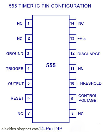
ELEX IDEA BLOG: IC 555 BASIC PRINCIPLE & THEORY

Adjustable Timer Circuits Using IC 555

Astable Multivibrator using 555 Timer
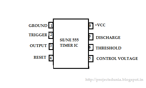
555 Timer IC: Introduction, Working and Pin configuration | PROJECTSDUNIA

8051- AVR - PIC MICROCONTROLLER PROJECTS: 555 Timer IC Pin configuration

Simple Time Delay Circuit using 555 Timer – ArRoboticsBlog

555 Timer IC - Pin Configuration, Modes & Its Applications