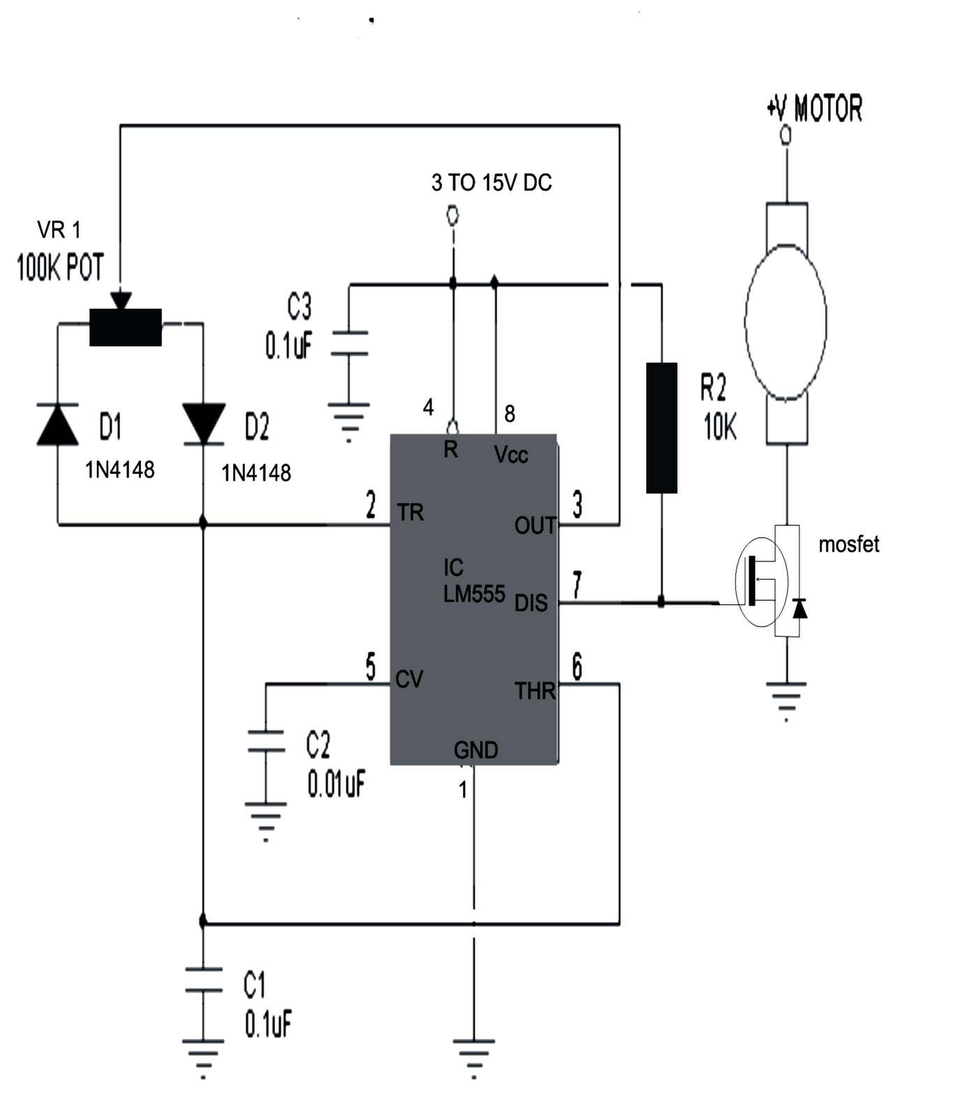
Pwm Motor Control Circuit
Ic555 motor speed controller using pwm Pwm tl494 motor control 12v speed circuit controller dc 24v using project source Dc motor speed control pwm circuit
PWM
Motor direction mosfet pwm dc driver based arduino controlled controller stuck reversing high voltage Pwm dc motor control speed electroboom voltage circuit using amp op power supply ac increase when toothbrush electric arduino fans Motor dc pwm circuit control speed 555 variable ic rpm l293d components required
12v-24v pwm motor controller circuit using tl494-irf1405
Building a pwm circuit to control a 90v dc motor at 20amps. will thisPwm motor control Pwm circuits ic555 pcbPwm control.
Motor circuit dc speed pwm controller control simple circuits diagram brushed 24vdc based ic make schematic mosfet 555 use potentiometerMake this pwm based dc motor speed controller circuit Pwm motor control circuit notes diagramPwm control motor schematic.

Motor circuit dc pwm control 90v building speed schematic electrical 20amps work will resistors ballast electronics stack
.
.


DC Motor Speed Control PWM circuit

PWM

Building a PWM circuit to control a 90v DC motor at 20amps. Will this

12V-24V PWM Motor controller circuit using TL494-IRF1405

PWM Motor Control

arduino - PWM controlled MOSFET based DC motor driver, stuck with

pwm control | ElectroBoom